Knowledge Hub: Engineering High-Performance Custom Aluminum Enclosure Solutions for Optimal Signal Integrity
In next-generation telecommunications, the boundary between mechanical engineering and electromagnetic performance has completely dissolved. As global infrastructure rapidly transitions into higher frequencies—such as Ku-band (12–18 GHz), Ka-band (26.5–40 GHz), and E-band (60–90 GHz) LEO satellite networks—achieving a high-performance Custom Aluminum Enclosure and precision mechanical structures has become increasingly critical to overall communication system performance, thermal stability and long-term reliability.
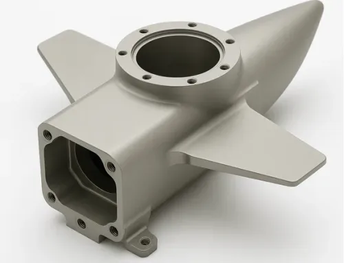
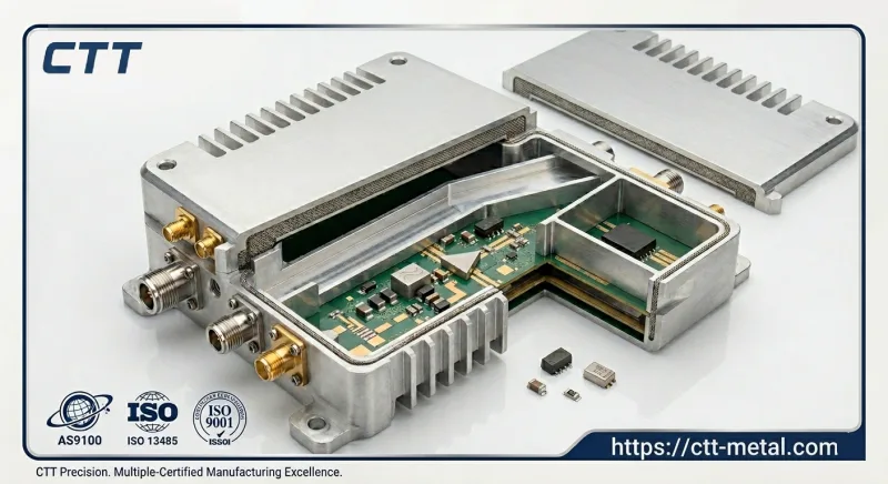
An advanced RF communication housing is no longer just a passive metal protective box; it operates as an active component of the RF ecosystem. Even a micron-level deviation in cavity flatness or a microscopic warp in a thin-wall Custom Aluminum Enclosure structure can alter electromagnetic coupling pathways, induce catastrophic phase errors, or lead to devastating signal attenuation.
The Crucial Intersection of Mechanical Tolerances and RF Physics in a Custom Aluminum Enclosure
When routing high-frequency microwave and SATCOM signals, standard CNC manufacturing limits are no longer sufficient. At Ka-band frequencies (30 GHz), the skin effect dictates that 95% of the RF current flows within the top δ ≈ 0.48 μm of the aluminum surface.
Consequently, precise mechanical properties directly dictate electrical outcomes:
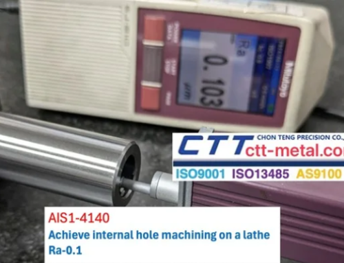
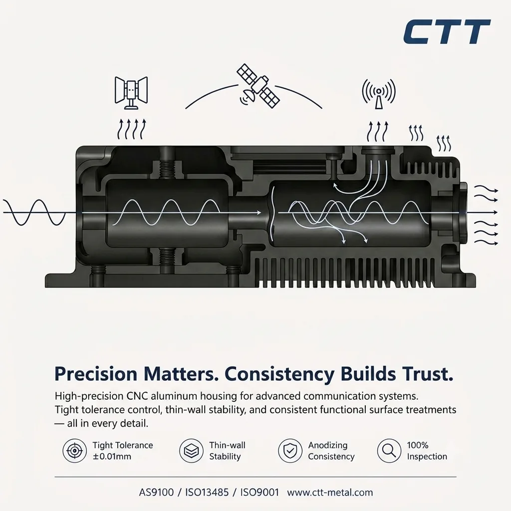
Surface Roughness (Ra) and Attenuation: Any machining ridges left by a CNC tool tip increase the effective electrical path length and cause severe insertion loss. Internal wave-guiding cavities within the CNC Aluminum Enclosure must achieve a surface finish of Ra ≤ 0.4 μm (with critical paths optimized via diamond milling to Ra ≤ 0.1 μm), maintaining a dimensional tolerance of ±0.01 mm.
Micro-Level Cavity Flatness & PIM Prevention: In high-power transponders (>100W), microscopic gaps at housing-to-cover interfaces create non-linear metal-to-metal contacts. Enclosure mating surfaces must guarantee a flatness tolerance of ≤ 0.02 mm over a 100×100 mm area under a specified torque profile to eliminate Passive Intermodulation (PIM) below -160 dBc.
Thin-Wall Geometry Stability: Reducing payload weight for aerospace applications requires pocket walls machined down to 0.5–0.8 mm. These thin-wall structures must exhibit zero resonance or deflection under launch vibration loads (20–2000 Hz, up to 14.1 g_RMS) to avoid shifting the center frequency of integrated filters by even 0.05%.
Overcoming Extreme Thermal Loads and EMI Challenges
Modern Solid-State Power Amplifiers (SSPAs) within satellite payloads generate intense localized heat fluxes, often exceeding 50W/cm². Operating environments demand strict temperature control, restricting junction temperatures (ΔT_j) to ≤ 85°C from ambient deep-space exposure (ranging from -40°C to +125°C). Because aluminum alloy AL6061-T6 has a Thermal Expansion Coefficient (CTE) of 23 × 10⁻⁶/K, unmanaged thermal gradients will induce structural expansion, distorting the precision cavities.
To maintain absolute operational reliability, modern hardware demands a consolidated approach that integrates tight-tolerance 5-axis CNC machining with precision EMI shielding and highly consistent functional anodization:
The Anodization Dilemma in EMI Shielding: Standard Type II Anodizing creates an aluminum oxide (Al₂O₃) layer that acts as an electrical insulator with a high dielectric breakdown voltage (>500V). To ensure a continuous, low-impedance Faraday cage providing >80 dB attenuation from 1 to 40 GHz, advanced chemical masking must be utilized during surface treatment. This leaves pristine bare metal—treated strictly with conductive Chromate Conversion Coating per MIL-DTL-5541 Type II Class 3 (surface resistance <5 mΩ/sq)—strictly along the EMI gasket seating grooves.
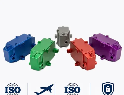
Precision Anodizing Dyeing for Thermal Radiation Optimization in a Custom Aluminum Enclosure
Exterior surface modification of a Custom Aluminum Enclosure is not merely cosmetic; it is a critical thermal management process. In deep space or high-altitude environments where convection is non-existent, radiation is the primary mechanism for heat dissipation.
Controlled Oxide Layer for Dyeing: Utilizing MIL-A-8625 Type II Class 2 (Dyed) anodizing, the anodic porous layer thickness is precisely controlled between 12 μm and 18 μm. A layer thinner than 10 μm fails to retain sufficient organic/inorganic dye molecules, leading to color shifting under UV exposure, while a layer thicker than 25 μm increases thermal resistance.
Matte Black Dyeing and Emissivity (ε): By implementing specialized inorganic cobalt sulfide or organic matte black dyeing, the surface solar absorptance (α) is engineered to 0.92–0.96, and more importantly, the hemispherical thermal emissivity (ε) is driven up to 0.85–0.90. This specific optical property optimization maximizes the enclosure’s passive radiant cooling capacity into the cold vacuum of space (4K).
Sealing Process Control: Post-dyeing, a hydrothermal sealing process using nickel acetate (5–8 g/L at 96°C–98°C, pH 5.5–6.5) is executed for 15–20 minutes. This closes the oxide pores, locking in the pigment and ensuring zero outgassing (Total Mass Loss, TML < 1.0%; Collected Volatile Condensable Material, CVCM < 0.1% per ASTM E595)—a strict mandate for space flight hardware.
Eliminating Risk with Aerospace-Grade Certification for Your Custom Aluminum Enclosure
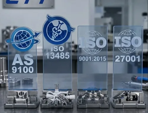
The technical complexity of fabricating these components leaves zero margin for error. For global procurement teams, selecting an AS9100-certified manufacturing partner is the ultimate strategic step to eliminate quality volatility and guarantee mission-critical performance from the ground station to orbit.
A multi-certified quality management infrastructure—spanning AS9100 for aerospace, ISO 13485 for medical-grade precision, and ISO 9001—underpins every single step of the manufacturing lifecycle. This robust cross-industry expertise ensures 100% material traceability of aerospace-grade alloys (such as AL6061-T6 or AL7075-T6 via Mill Test Reports), rigorous coordinate measuring machine (CMM) inspection protocols verifying geometries down to ±2 μm, and flawless surface treatment consistency.
Whether you are developing complex CNC Aluminum Enclosure systems or high-frequency waveguide components, partnering with a precision manufacturer that bridges the gap between mechanical tolerances and RF physics is the only way to guarantee long-term stability for demanding communication applications.
Surface Roughness & Attenuation
Core Challenge: Tool marks increase effective electrical path length, causing severe insertion loss.